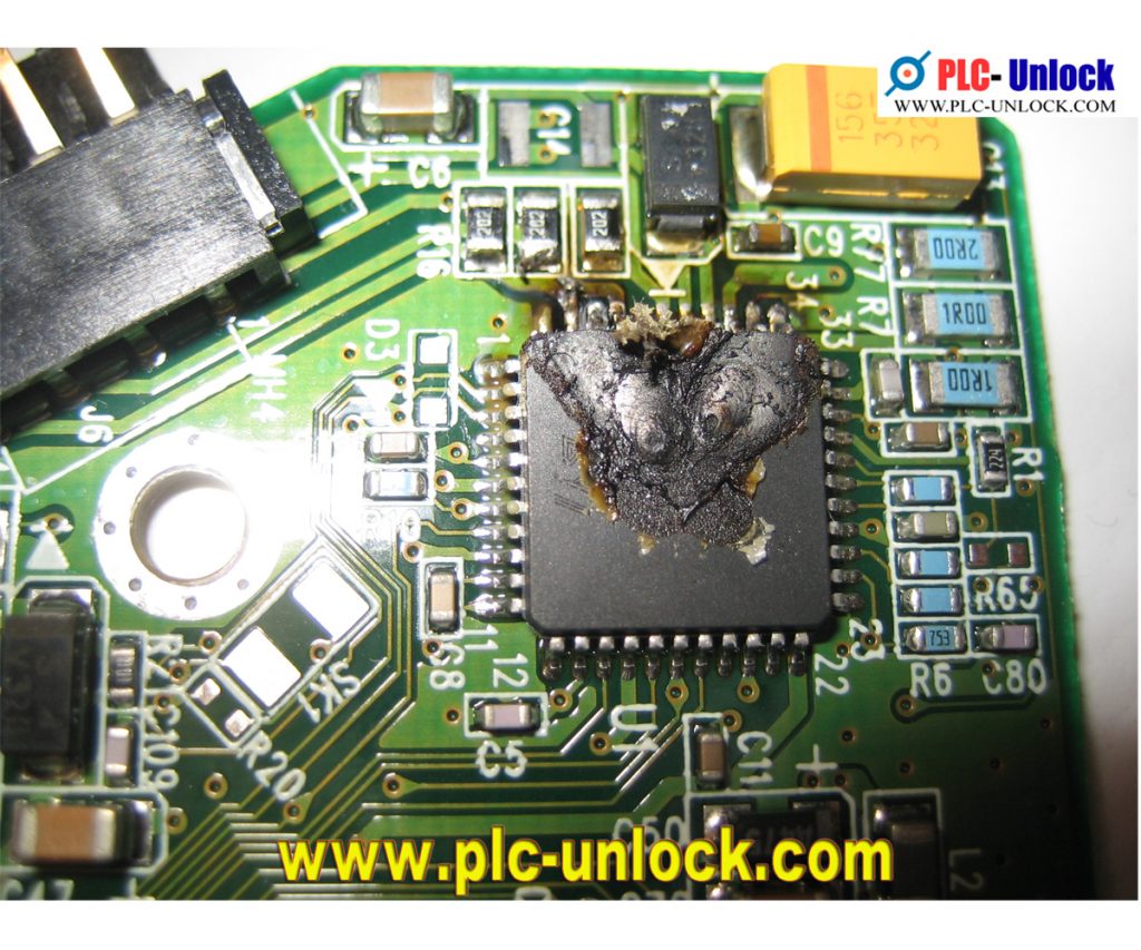
If have plc cpu has damaged or burned case happened. That time it will send to us for recovery to get plc or hmi program. If it not possible to send us that time you get our suggestion how to recovery from damaged circuit.
Troubleshooting inputs and outputs of PLC’s:
Now on to the more common problem of troubleshooting inputs and outputs. The primary goal of I/O troubleshooting is to find out why the internal status of the PLC (what the PLC thinks is happening) does not agree with the external situation (what is actually happening). The first thing that must be done is to determine the relationship between physical I/O modules and the I/O instructions in the PLC program. This is done by using the addressing scheme for the particular PLC that you are working on, and this scheme differs from one manufacturer to another. Somewhere in the documentation there will be an explanation of how to determine which physical I/O point a specific program address is connected to and vice versa. Once this scheme is understood, each problem can be isolated to a single I/O module and a program monitoring device (usually a hand held unit, terminal, or personal computer) can be used to check the internal status of the input or output in question.
Troubleshooting digital input modules:
The function of a digital input module is to determine the ON/OFF status of a signal or signals in the external world and communicate that information to the PLC processor. Most digital input modules detect changes in voltage levels, and they are available with various AC, DC, or universal ratings, with universal modules typically accepting a fairly wide range of either AC or DC signals. A typical AC input channel is shown in Fig. 2. Note that the figure shows indicator lamps on both the power and logic sides of the circuit; many modules, however, have only one or the other of these. If only one indicator is present, it’s important for troubleshooting purposes to determine where it is connected. If the threshold unit on an active input has failed, for example, a power-side indicator would be ON while a logic side indicator would be OFF.

The power to drive PLC inputs usually is not supplied by the input module, so it’s important to find out where that power comes from. There are two types of inputs: Isolated and non-isolated. Troubleshooting differs depending on which type you are dealing with. Each channel on an isolated input module is electrically separated from the others and may have a different source of power. On the other hand, one side of each input channel on a non-isolated module is connected to a common reference.
Determine if the power for the input in question is present, as faults in field wiring and devices can blow a fuse, trip a breaker, or cause some other power disruption. If input power is not present, determine and rectify the cause of the failure before proceeding.
If input power is present, connect a voltmeter across the input as shown in Fig. 3, actuate the input device in the field, and measure the voltage at the PLC input to determine if it changes adequately when the field device changes state. If it does not, the field device or wiring are most likely at fault. If a proper voltage change is observed, the power and/or logic indicators on the module should change when the voltage does, and the addressed location in the PLC, when monitored with the programming device, also should change state. If the indicators do not properly reflect the state of the input, replace the input module.
If the input module is working properly but the PLC still is not registering the input internally, the problem lies in the system used to communicate input information from the module to the processor. Consult the manufacturer’s documentation to determine how to troubleshoot this equipment, which may include an I/O rack, back plane, communication module, and cabling.
Troubleshooting analog input modules:
Instead of monitoring the on/off status of an input, analog inputs measure the actual value of a voltage or current and communicate it to the processor. Analog input modules are available in many DC voltage and current ranges, and basic troubleshooting is almost identical to that for digital modules.
First determine if the input is isolated or non-isolated, and determine the source of power and verify that it is present.
Next, change the voltage or current level generated by the field device, verify that the change is reflected at the input module terminals, and verify that the content of the address associated with the input reflects the voltage or current change.
There are two additional complications introduced by analog modules, however. First, there usually is no indication on the module to reflect the level of the input, so an external meter must be relied upon. Second is the scale problem: You must determine what range of voltage or current the module is designed to measure, and what numerical scale is associated with that range in the PLC. An input with a 1-5 VDC range may be expected to generate a change from 0 to 1000 in a PLC register, for example. Just determining if the number changes when the input does is not enough. A good approach is to adjust the external voltage or current to minimum, half scale, and maximum values, and to observe the PLC register to determine if corresponding changes have occurred. In the previous example, 1 VDC should generate 0 in the PLC register, 3 VDC should generate 500, and 5 VDC should generate 1000. If the field device cannot be easily manipulated in this manner, it can be temporarily replaced for troubleshooting purposes by a signal transmitter.
Troubleshooting digital output modules:
Output modules are designed to cause some change in the external world in response to an instruction in the PLC processor. Digital outputs will often be used to perform tasks like starting motors, turning on indicating lights, and energizing solenoid valves. Many different digital output module types are available, with the most common varieties being DC outputs that rely on transistors as switching devices, AC outputs that rely on trials, and universal outputs that use relay switching. Both power and logic indicators are shown once again, but as in the case of digital inputs, only one or the other may actually be present.
The power to drive PLC outputs, like inputs, is usually not supplied by the module, so it’s important to find out where that power comes from. Once again, there are isolated and non-isolated modules, and troubleshooting differs depending on which type you are dealing with.
Again, the first step in troubleshooting is to determine if the power for the output in question is present and to restore that power if it is not. There is a further complication to troubleshooting most output modules, because they typically contain a fuse to protect the output switching device. Faults in field wiring and devices can blow that fuse, so its condition must be verified before proceeding. Many modules are equipped with a “fuse blown” indicator that shows which channel or module has a blown fuse. These fuses may be accessible from the front of the module, or the module may have to be removed or even disassembled in order to gain access to them.
Once power has been verified and the fuses checked, the procedure for troubleshooting digital outputs is somewhat the reverse of that for digital inputs.
First the programming device must be hooked up to the PLC, and the address that is associated with the output in question must be determined. The output then can be “forced” ON or OFF internally in the PLC, and the module can be observed for a reaction. If the indicators on the module do not reflect the forced condition, change the output module. If the module is working properly but still does not react to the forcing, the problem again lies in the communication between the processor and the module, and the manufacturer’s documentation is your best source for troubleshooting information.
If the voltage is not changing, the problem can most likely be found in the field wiring. If the field wiring is in doubt, it can be temporarily disconnected and a test load can be connected to the module. If the test load operates properly, the problem lies in the field wiring or field device. It’s important that a test load be used as opposed to just disconnecting the field wiring. Because they leak a small amount of current in the OFF state, the voltage at most solid-state outputs will not change a large amount as the output device is switched with no load. A properly sized resistor, solenoid valve, or relay coil provides a good test load.
Troubleshooting analog output modules:
Analog outputs are used to generate a variable voltage or current typically used to perform tasks like throttling the speed of a variable speed drive, adjusting the position of a control valve, or driving a panel indicator. As with input modules, analog output modules are available in many DC voltage and current ranges. Usually, there is no indication on the module to reflect the level of the input. As such, you must determine what range of voltage or current the module is designed to produce and what numerical scale is associated with that range in the PLC. An output with a 4-20 mA DC range may be expected to react to a change from 0 to 1000 in a PLC register, for example.
A good approach to testing analog outputs is to “force” the number in the PLC register associated with the output in question to minimum, half scale, and maximum values, and to measure the voltage or current generated at the output. In the previous example, a 0 in the appropriate PLC register should generate 4 mA at the output terminals, 500 should generate 12 mA, and 1000 should generate 20 mA. If the field wiring or field device are in doubt, they can be temporarily disconnected and replaced by a test load. If the proper currents or voltages are not measured at the test load, the analog output module should be replaced. A properly sized resistor, typically between 250 and 1000 ohms, is usually used as a test load in analog circuits.
Address: a numbered location (storage number) in the PLC’s memory to store information.
Analog input: A varying signal supplying process change information to an analog input module.
Analog output: A varying signal transmitting process change information from an analog output module.
Central processing unit (CPU): An integrated circuit that interprets, decides, and executes instructions.
Input module: A component of a PLC that processes digital or analog signals transmitted from field devices.
Output module: A component of a PLC that controls field devices.
Program: One or more instructions or statements that accomplish a task.
Programming device: A device used to tell a PLC what to do and when it should be done.
RELATED ARTICLE: A PLC IS NOT A “BLACK BOX” . . . OR IS IT?
While working as a student engineer on a coop assignment in a hardboard siding manufacturing plant, I had the opportunity to participate in the design and installation of the first PLC-based control system ever installed in the plant. This project represented a major commitment for the company to a new technology, and my boss and I were determined to make it a success. We went to great lengths to alleviate fears of the new technology among our maintenance electricians, who questioned the replacement of well-understood relay logic with an electronic “black box.” We repeatedly explained the advantages of the PLC, including the simplicity of wiring, the usefulness of indicator lights on input and output modules for troubleshooting, and the similarities between ladder-logic programming and relay control.
Just when we thought the situation was under control, we received a call from the electricians assigned to the project announcing that the “black box” had arrived. Upon repeating our reasons for believing that the PLC was a useful, flexible controller and not a mysterious black box, we were told to come and take a look for ourselves. When we did, we discovered the reason for the renewed concern. Unpacking the new PLC had revealed a rectangular metal box . . . painted black.